
Thread: Rotating Ballnut - design ideas
Threaded View


-
26-11-2016 #11

 Last Activity: 12-01-2017


First post on this bulletin board; I enjoyed this thread...or at least what I had a chance to read using the spotty WiFi signal at work anyhow.
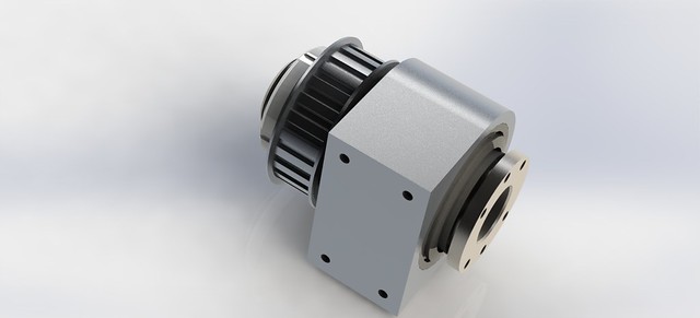
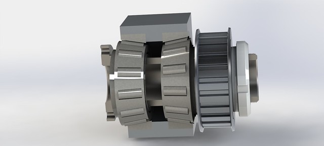
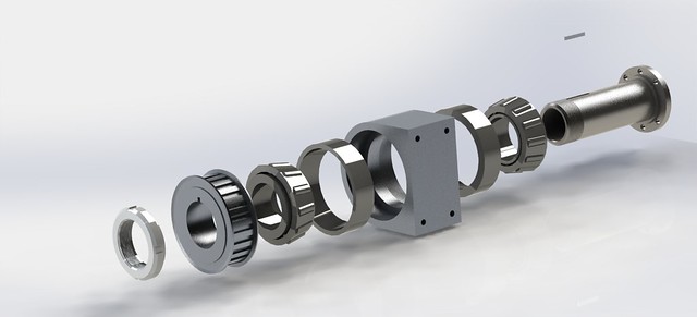
I find myself in need of a couple of rotating ballnuts for a 3000mm-long 2505 ballscrew, and have come across this older thread on the subject. I was inspired by the designs depicted here, and worked to duplicate/improve upon them when I became curious as to why angular-contact ball bearings were used instead of tapered roller bearings.
I'm trying to keep the unit as compact as possible and I suspect that the tapered roller bearings will help in that respect. The force on the hollow rotating shaft will be primarily axial, along the ballscrew axis with barely any radial load being applied by the tension of the timing belt/pulley.
I came up with the following design (sorry for the seemingly random view angles)--Any comments/input regarding it's viability?:
Thanks,
--MarkLast edited by SafeAirOne; 26-11-2016 at 09:32 PM. Reason: Typo/spelling

 Reply With Quote
Thread Information
Users Browsing this Thread
There are currently 1 users browsing this thread. (0 members and 1 guests)
Similar Threads
-
Rotating Ball nut
By drumsticksplinter in forum Lead Screws, Nuts & SupportsReplies: 30Last Post: 12-05-2020, 08:01 PM -
Interesting Papers on heavy duty design, vibrations, composites and column design
By D.C. in forum Gantry/Router Machines & BuildingReplies: 15Last Post: 25-06-2016, 10:13 PM -
Rotating Ballnut Design MK3
By Jonathan in forum Linear & Rotary AssembliesReplies: 0Last Post: 15-12-2013, 01:35 PM -
advice on floating bearing - outer ting rotating
By dsc in forum Lead Screws, Nuts & SupportsReplies: 8Last Post: 18-11-2013, 02:23 PM -
Design help etc required with DIY CNC Router Design / Build
By MikeyC38 in forum Gantry/Router Machines & BuildingReplies: 12Last Post: 21-10-2011, 04:50 PM

Bookmarks