
Thread: Initial Design Check Please
-
25-10-2014 #1

 Last Activity: 08-10-2019


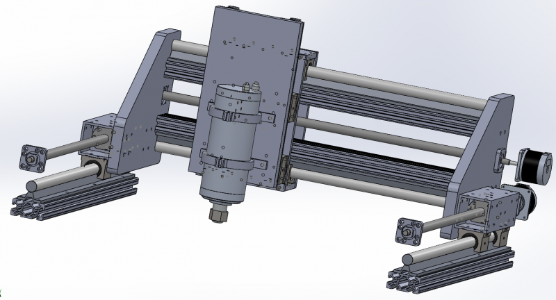
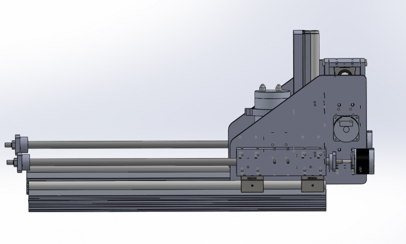
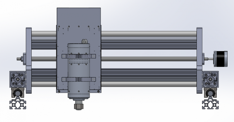
Hello, im looking to build my first CNC, so i have been lurking around here for a while now looking and reading up. I recently met the builder of SweetDream at the engineering show, who gave me some great pointers and as a result i have altered my design more.
So im looking at building it 500mm x 400mm with 100mm Z axis. Im looking at using SRB20 supported rails and 1604 ballscrews throughout the design. I still need to do more drawing as you can tell ie the rest of the frame below the y axis rails, but if anyone can spot anything that would be great.
The gantry side plates and main spindle plate will be from 6082 20mm aluminium, and the box that wraps round the rails on the x axis will be from 6082 10mm aluminium. The gantry side plates will be joined to the y axis bearing blocks via 60x60mm x 4mm thick aluminium box and inside that i have mounted the ball nut into an aluminium block which is then joined to the aluminium box.
Trev
-
25-10-2014 #2
Last Activity: 25-02-2015

It will help with advice if you mention what materials you're intending to cut.
-
25-10-2014 #3
Last Activity: 08-10-2019
Sorry my mistake. I would like to mill plywood, carbon fibre and aluminium.
Im looking to make the frame it will sit on out of 50mm steel box. Just got to find a local welder.
Trev
-
25-10-2014 #4
 Last Activity: 19-01-2024

Like Ian asks materials to cut will help but I've got a few why's.?
Why supportedround rails.?
Why 1604 ~(Do you mean 1605 ballscrews)
Why that size Profile.?
Why is there No bed.?
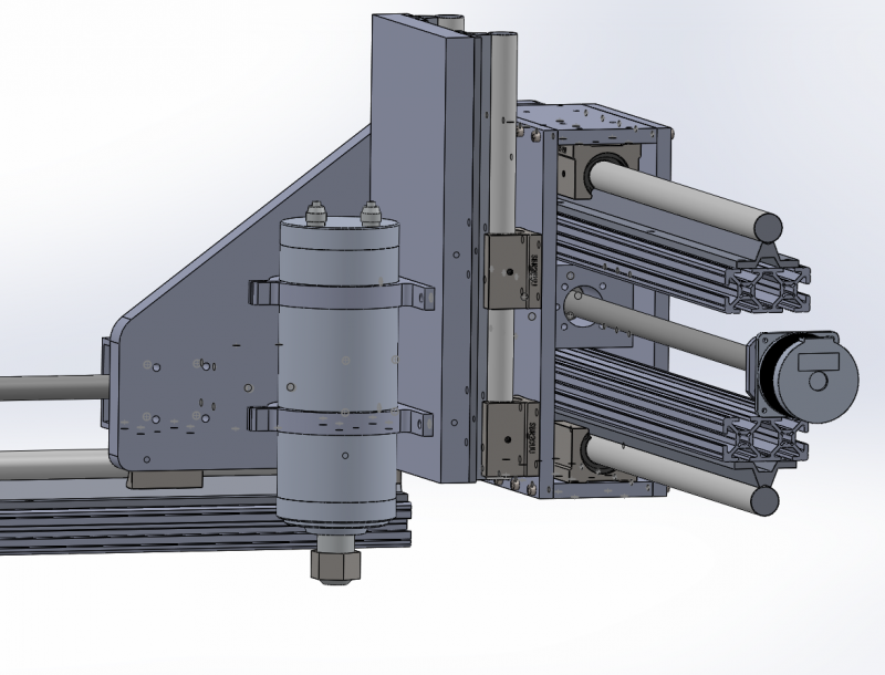
Got few a suggestions as well. Would make it so the Gantry sit directly on the bearings rather than between the bearing with brackets. This will make it easier to build and setup along with making accurecy easier to find. The way you have it will be much harder to setup without causing binding to bearings etc than sat directly on bearings.
Don't wrap a box around the gantry it doesn't add any strength really and makes setting up harder with bigger potential for causing binding bearings. The extra weight just means less potential acceleration.
Use thicker Rear Z axis plate as 10mm isn't enough and any resonance here will transfer to the finish quality.
Better if you can get the ballscrews down the side out the way as being stuck up high like that they are open to being lent on or caught with material when loading etc.
You don't show any lower frame so it's hard to tell what you thinking here but just bare in mind the base is the foundation for everything else so if this isn't accurate or strong it will impact the rest of the machine in a negative way.!!
-
25-10-2014 #5
Last Activity: 08-10-2019
Hi thanks for the reply
I went with the supported rails due to profile ones being out of my budget
yes they are 1605
i went with that profile as it lined up nicely with the holes in the supported rail, making it easy to join the two.
Sorry i know having no bed and lower frame makes it tricky to check, its just i wanted what i had drawn checking first in case my design is junk.
With regards to mounting the bearing blocks to the gantry sides, do you mean by bolting a plate to the bottom of the gantry side and then the bearings to that, forming like an upside down T shape?
Ok i will make the plate 20mm and remove the rear plate on the gantry. I saw the idea originally on the Sweetdream CNC which did seem like a good idea.
Is there any good reference design on this website i could look at at all?
Thanks again
Trev
-
25-10-2014 #6
Last Activity: 19-01-2024
Well if you haven't bought them already this is worth re-thinking. Profiled linear rails from china are now quite cheap and the difference isn't worth not using them.
 Originally Posted by Gotty101

Well this again is worth reconsidering. 5mm pitch is fine for harder materials like aluminium but does restrict the speed for cutting woods and plastics correctly. 10mm is a better balance and while more biased towards softer materials it's still gives more than capable resolution for aluminium. Originally Posted by Gotty101
If you connect to the screws with timing belts, which I suggest you do for resonance reasons, then it's an easy ratio change to increase resolution if you ever find your mostly cutting harder materials which need torque and resolution.
Ok ye thought that may be case but layed flat like that weakens the material unless it's well supported from below which could be ok for the base if supported from below but the Gantry has is designed can't be so positioned like that so it will be weak in one direction. I'd think about using square rather than rectangle and beef it up a little, say 80x80 or 90x90, or go with "L" sahpe setup like I've posted on forum many times which is stiff in both directions. Originally Posted by Gotty101
Something like this I knocked up to show both screws and gantry but with a little more bracing etc. There's many ways but sat on the bearings is strongest and easier to do. Originally Posted by Gotty101
Argh but he's only used to taking Pics of UFO's and knows nothing about CNC.! . . Lol . . ( Originally Posted by Gotty101
 He's a mate not being rude.!!)
Last edited by JAZZCNC; 25-10-2014 at 08:03 PM.
-
The Following User Says Thank You to JAZZCNC For This Useful Post:
-
26-10-2014 #7
Last Activity: 08-10-2019
Thank you JazzCNC,
That really cleared things up, expecially with the pictures.
With regards to the profile rails i had a look on ebay and they seemed to get quite $$ when i was looking at the longer lengths, but ive found them on aliexpress and they seem alot better priced and with more options, is this where you get yours from?
i had a look for the Z axis for example and found these rails
http://www.aliexpress.com/item/EGR15...828633643.html
and these blocks
http://www.aliexpress.com/item/1PC-H...044267870.html
Are these the right kind of thing? Only reason im asking is there seems to be different versions ie HGR MGN.
Sorry about all the questions.
Thanks again
Trev
-
26-10-2014 #8
 Last Activity: 01-05-2026

I would advise against the 15 size, the bearing blocks are an absolute pain to grease, go with 20's all round.
Last edited by EddyCurrent; 26-10-2014 at 10:54 AM.
Spelling mistakes are not intentional, I only seem to see them some time after I've posted
-
26-10-2014 #9
Last Activity: 19-01-2024
Hi Trev, Originally Posted by Gotty101
No problem with questions that's why we are here to help each other and ask questions. Don't stop asking questions no mattter how daft they may feel, if your not sure ask.!!
Regards the rails and bearings then like eddy says 20mm tend to be a better size and not just for greasing, they make building the Z axis easier due to being taller and generally give better support with there larger bearings. The rails also sit on the profile better.
With the type then look on the Hi-win site and it will show the difference between the types, it's often very subtle differences like hole centres or bearing heights ratings etc.
Most use the HGH-CA for the slim type and the HGH-CW for the flanged wide type with standard pre-load Z0. If your wondering what pre-load means then it's the amount of pre-tensioning the bearings have when on the rails. Pre-loading removes any slop or play but at same time requires more force to make the bearings slide so we don't want it too high. Z0 is lower pre-load.
Those new to using profiled linear rails are often shocked to find that the bearings don't easily slide when on the rails but require a good shove and then stop quickly. This preload at work. Stand on the buggers and you'll end up on your arse as they work best under pressure and glide like on ice. .. Lol
If your buying from Ali express the look for Fred Lee. Personally I buy ballscrews and rails etc from from Chai at linear motion bearings but he doesn't sell Hi-win brand of rails, they are some other Taiwanese brand which can't think of at minute but they are very good quality do just the same job and a little cheaper.Last edited by JAZZCNC; 26-10-2014 at 03:03 PM.
-
26-10-2014 #10
Last Activity: 08-10-2019
Thanks guys for the help so far. ive scrapped and started from scratch. Ive based it heavily off the pics you posted Jazzcnc, they where a great help and have used 20 Hiwin rails as suggested. Ive done everything in 20mm ali and doubled up on the aluminium profile now. Ive still got a fair bit to draw like the lower frame and bed and stepper mounts with belt drives, and y axis ball screws. Unfortunately im off for a short break so im going to have to go cold turky from solidworks for the next few days.
im going to have to find a good source of 20mm plate next. I was talking to a close family friend about my project who is an ex tool maker so now i have access to his machine shop now which is a great help.
Thanks again all
Trev

 Reply With Quote
Thread Information
Users Browsing this Thread
There are currently 1 users browsing this thread. (0 members and 1 guests)
Similar Threads
-
Initial workpeice tooling set-up instructions using a pendant controller type machine
By Nthkentman in forum Machine DiscussionReplies: 25Last Post: 30-08-2014, 08:33 PM -
Component Check
By manofgresley in forum General ElectronicsReplies: 1Last Post: 22-04-2014, 06:04 PM -
Initial thoughts on new build
By Neale in forum Gantry/Router Machines & BuildingReplies: 4Last Post: 25-01-2014, 11:05 PM -
Some initial questions....
By andy586 in forum Gantry/Router Machines & BuildingReplies: 5Last Post: 27-01-2013, 03:00 PM -
Newbie Initial Wiring/Setup
By Rikk in forum Motor Drivers & ControllersReplies: 3Last Post: 28-06-2011, 10:19 AM

Bookmarks