
-
09-07-2015 #151

 Last Activity: 13 Hours Ago

 So does that basically activate when the proximity sensor is happy? So its a locator device?
 Originally Posted by i2i

-
09-07-2015 #152
 Last Activity: 25-10-2022

there's a point on the disc that is removed, this activates the sensor when it passes it. The logic in the macro needs to see this twice for one tool position
-
17-07-2015 #153
Last Activity: 13 Hours Ago
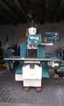
Hi, so update time. Mostly there now, busy wiring in the DC Drive input isolator. I just want to check, some of the wiring a bit uncertain about.
This is the board I am using, as recommended by i2i.
http://diycnc.co.uk/spindleV5x.pdf
On the board, I need to provide 24V DC, straight forward, I take from my 24V PSU rails.
I then need to provide the 0-10V output to the old DC drive, check, 2 wires, sorted.
I then need to provide GND, STEP, DIR and Run / Enable.
From my CS Labs unit IP-A, I get an Analog Output.
So, looking at the image below, I take from pin 7 (Analog Out 0) and pin 20 (Gnd) - do these go to the GND and STEP inputs on the board?
What do I use for DIR And Run / Enable then? Are these from my CS Labs unit (24V switched outputs)?
-
17-07-2015 #154
Last Activity: 1 Day Ago


Chas I don't see an image!!
..Clive
The more you know, The better you know, How little you know
-
18-07-2015 #155
Last Activity: 25-10-2022
Gnd. Gnd
Step. This is a 5v logic level pulse and is normally a configured output from the parallel port that gives 2000 pulses for full output, which will be 10v dc.
Dir. This is a 5v logic level relay.
Run. This is a 5v logic level relay.
The board is basically a DC isolated frequency to voltage converter with two added relaysLast edited by i2i; 18-07-2015 at 01:47 AM.
-
18-07-2015 #156
Last Activity: 01-04-2021
I am not sure what you are going to do with this board, the CSMIO/IP-A does not have any step and direction output, the controller has a 0-10V output that goes to the spindle speed control. If you need isolation because the current spindle has no isolation, then you are better to just throw the spindle away and stick an inverter and ac motor in the system.
Originally Posted by Chaz
-
18-07-2015 #157
Last Activity: 13 Hours Ago
Sorry, I copied / pasted the post and was surprised as I could see it. Clearly no one else can ;p Originally Posted by Clive S
See below.
-
18-07-2015 #158
Last Activity: 13 Hours Ago
Ye, its just more money though that I dont need to spend. Originally Posted by dodgygeeza
Ill rather get this working, if someone can help with an isolation option / circuit and then later look to put in a higher speed spindle which will be useful for cutting the items I want to cut.
-
18-07-2015 #159
Last Activity: 25-10-2022
Chaz send an email to Roy and ask him if the dc-dc converter is 1:1. If so you can probably run the ipa 0-10 through it instead of the generated voltage from the diy cnc board. ( please check this with Roy first ) Originally Posted by dodgygeeza
-
18-07-2015 #160
Last Activity: 13 Hours Ago
Thanks - just done.
Will wire up to be manually set for speed until I get some options.
Could I use the 5V from the Encoder output terminals on the CS Labs unit to allow me to enable the board? I dont have any other 5V supplied that I can use.Last edited by Chaz; 18-07-2015 at 09:34 AM.

 Reply With Quote
Thread Information
Users Browsing this Thread
There are currently 1 users browsing this thread. (0 members and 1 guests)
Similar Threads
-
FOR SALE: Denford Triac CNC PC
By ricey3 in forum Items For SaleReplies: 6Last Post: 10-01-2017, 01:39 PM -
Help Denford triac p.c.
By mikeulike in forum Denford MillsReplies: 3Last Post: 02-06-2015, 03:59 PM -
eBay: Denford Triac with Mach3 Conversion
By large519 in forum Items On eBay UKReplies: 0Last Post: 29-04-2015, 05:34 PM -
CONVERSION: Denford Triac Mach3 conversion
By rnr107 in forum Conversion Build LogsReplies: 11Last Post: 23-10-2014, 02:44 PM -
WANTED: Denford Triac
By edwardsjc in forum Items WantedReplies: 13Last Post: 20-08-2012, 08:17 AM

Bookmarks